Often times, a remote location requires high availability. This high availability will include two separate routers, each with their own WAN circuit connecting back to the Data center.
In order for workstations at the remote site to be able to utilize the “active” router a FHRP (First Hop Redundancy Protocol) must be used. There are three major FHRPs: HSRP (Hot Standby Router Protocol), VRRP (Virtual Router Redundancy Protocol), and GLBP (Gateway Load Balancing Protocol). VRRP is a standards based FHRP while GLBP and HSRP are Cisco proprietary FHRPs.
In Cisco only organizations, HSRP has a higher tendency to be used as an FHRP and will be covered today. With HSRP, a virtual MAC address is used to respond to ARP requests from workstations trying to resolve the MAC address of their default gateway. Within HSRP, the Active router is determined based on priority (default priority is 100). The highest priority router becomes the active router for the HSRP group. The HSRP active router handles frames destined to the virtual MAC address and forwards traffic normally. 
Figure-1 HSRP: Normal Operations
In the event of the HSRP active router failing, the standby router will take over and start handling traffic for the virtual MAC address. This allows for workstations to continue sending packets back to the Data center without requiring manual intervention of the workstations.

Figure-2 HSRP: Active Router Switchover

Lets now review a basic HSRP configuration. Within a basic configuration only two settings are required:
- The interface must be configured with its own unique IP address
- The standby group needs to be assigned it’s virtual IP address
In addition to the above two configurations, it is also recommended to set the priority on the desired active router to something higher than the default (which is 100). Preempt should also be configured as well on the routers, this allows for the router with a higher score to immediately take over as active.
Left router configuration:

Right router configuration:

As seen above, both routers have their own unique IP address on their interfaces while they share the same virtual IP address. In addition, the right router does not have a priority configured meaning it will use the default priority of 100.
Within a basic HSRP configuration, the only way a HSRP switchover occurs is when the heartbeat between the Active router and the Standby router is broken. This means that if a fail-over occurs upstream (BGP peering is lost, the WAN circuit fails, etc.) of the HSRP active router, the active router will stay active and end up causing a traffic black hole.
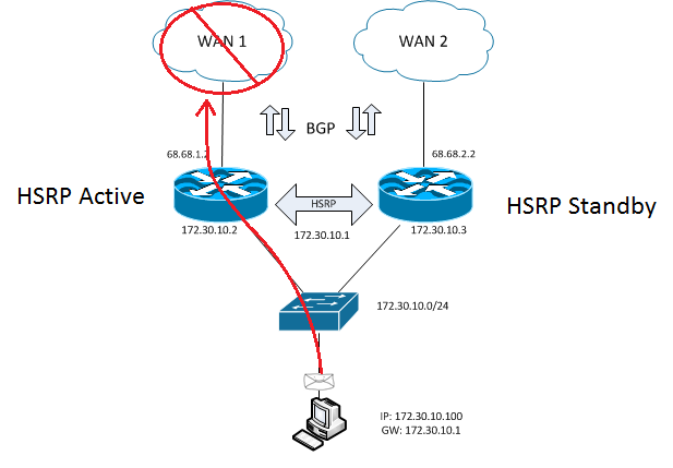
Figure-3 HSRP: Traffic Black Hole

HSRP supports the ability to track interfaces, IP SLA Objects, and IP SLA Object groups. In a typical HSRP configuration with tracking, interface tracking is used to track the upstream interface connecting to the WAN.
Interface tracking can be easily accomplished with the following command:
standby 0 track FastEthernet 0/1 25
The command itself is pretty explanatory, first you specify the standby group you are applying the configuration to. Next you specify what you are doing with the standby group (“track”). Then you specify what you are tracking, in this case it will be FA0/1. Finally, you give a value to how many points you want to decrement if the tracked object goes into a “down” state. In this scenario, where the active router has a priority of 110 and the standby router of 100, if the interface on the active router goes down it would loose 25 points from its priority making it 85. This score, which is lower than the default 100, would cause the standby router to take over as the active router to forward traffic.
The complete interface configuration with interface tracking looks like:

Lets now take a step back to look at the bigger picture to see why interface tracking only works for a small subset of WAN failures.
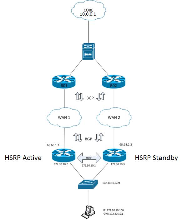
Figure-4 HSRP: The Bigger Picture

A typical HSRP configuration with basic interface tracking has the desired active router configured with a higher priority than the default priority left on the standby router. The active router than has interface tracking setup to track the interface connected to the WAN. If the tracked interface fails, the priority score is decremented to a score below the default priority (100) set on the standby router, allowing the standby router to take over as active.
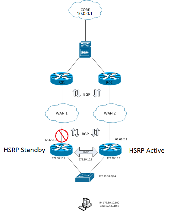
Figure-5 HSRP: Interface Tracking

During an upstream failure, basic HSRP tracking will not see the failure further up the traffic flow (the interface will stay up). This causes a similar traffic black hole situation seen earlier where the active router stays active but has no path back to the Datacenter.

Figure-6 HSRP: WAN Traffic Black Hole

With a more advanced tracking configuration it is possible to track further upstream either into the WAN circuit providers network or into the Data center itself. In order to track upstream, IP SLA (or IP SLA Object Group) is required to keep track of flow through the traffic path.
*********Read this part*********
There are a few considerations that must be made when implanting a more advanced tracking configuration:
- Does asynchronous routing negatively impact applications / services?
- Is there more than one Data center?
- Is there a routing protocol between the two routers?
If you answered yes to any of the above questions, the following configuration will cause routing problems in your network unless properly tweaked to handle return traffic from the WAN router(s) at the Data center(s), and to prevent routing loops between the two routers at the remote location.
*********I hope you read it*********
To combat an upstream WAN failure, IP SLA tracking will be implemented. Ideally you will already have an IP SLA responder somewhere in your Data center, but if there is none, any device can be used just remember that you want it to be very fault tolerant.
The configuration of the IP SLA for HSRP tracking has three parts; the IP SLA itself, the track object, and special attributes required for it to all work together.

The HSRP configuration itself will remain the same as before except instead of tracking the interface, the track object will be tracked
Lets break the commands down and review what each one does.
Within the ip sla 11 configuration there are two parts needed. The first section of the first part is icmp-echo states that the IP SLA test will be an echo and its destination. The second section is source-ip and is used to force the router to send its icmp from the interface that owns the IP address, in our case we want the WAN interface to be used (this prevents issues seen when the router is aware of the routes the other HSRP router has). The second part of the ip sla 11 command is the frequency at which the test will run, this is in seconds.
With the track configuration we create a track object (object 10 for this example), assign it to a ip sla (the ipa sla previously created), and reachability is used to inform the track object that the reachability of the IP SLA will be used for its state. Within the track configuration its possible to set a up and / or down delay. This delay is used to prevent a flapping state, and is tracked in seconds. A 15 second delay is a pretty safe delay to make sure the circuit is really down or really up, keep in mind that the up delay means that even though the IP SLA is down, traffic will still be forwarded into the probably black hole.
Finally we have two additional required configuration options. The first command, ip sla schedule 11 life forever start-time now starts the IP SLA which is used by the tracked object. It must be started otherwise the track object will be marked down. The command causes the IP SLA to start immediately and run forever. The second command, ip sla enable reaction-alerts allows for the IP SLA to be tracked properly through the system.
One change on the interface configuration will be required also, this is standby 0 track 10 decrement 50. This tells the router for the HSRP group to track object 10 and if it goes down to decrement the score by 50.
For completeness, the configuration of the other router is below:

There is no interface tracking on the standby router due to the fact that it is your standby device and decrementing points for HSRP would provide no positive impact. With that said, its possible to utilize the tracking configuration examples to build an EEM script for custom alerting (but that’s for another time).
As always, every network is different and careful consideration should be used before implementing any technology. It is always best to test!
Finally we will see the HSRP configuration in action. Below is the output from the Active HSRP router:

First we verify that it is in fact the active HSRP router. This is done by using the command show standby. As can be seen “Active router is local” which means it is in fact the active router. During this example, the interface on R01 was shutdown going into the WAN cloud this simulates the WAN circuit at the Data center failing but still leaving the remote locations as up and with BPG neighborship. IP SLA 21 was created to immediately announce the connection being down. this shows that IPA SLA 10 waits 15 seconds before triggering. Once triggered HSRP state moves into the speak state (the other router immediately takes over as active) and then into the standby state. We can then verify with show standby who the active router is, which in this case is no longer the local router.
Bonus (router taking back active role):


[…] covered HSRP (Hot Standby Router Protocol) in a previous post that went into great detail on how HSRP functioned and a few enhancements to it. This time around […]